News: development of the hardware accelerated graphics project funded by Nlnet Foundation
This project aims to provide a graphics server system based on hardware accelerated graphics, and a easy way to develop the graphics primitives. The accelerated versions runs faster using the exact same C code as the software version by automatic translation (transpiling) to Verilog code using a custom tool: https://github.com/suarezvictor/CflexHDL.
As an example, let’s see how to use and develop drawing privimites for solid rectangles and ellipses.
Ellipse case:
MODULE ellipse_fill32(
  bus_master(bus),
  const uint16& x0,
  const uint16& x1,
  const uint16& y0,
  const uint16& y1,
  const uint32& rgba, //color
  const uint32& base, //pixel offset
  const int16& xstride, //normally 1, but can run backwards
  const int16& ystride //bytes to skip for next line (usually the framebuffer width * 4 bytes)
  )
The bus argument is automatically handled both in software and in hardware by privided macros.
The rectangle primitive follows the same function signature.
You can directly call the function using compilation with a normal C compiler:
ellipse_fill32(BUSMASTER_ARG, x0, x1, y0, y1, rgba, base, xstride, ystride);The BUSMASTER_ARG macro is an automatic argument, defined on a provided header file. It’s useful for the implementation of the hardware accelerated primitive, as explained in the next section.
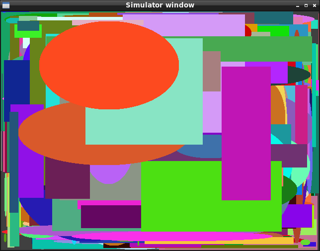
The following image is produced by the simulator by calling 1000 times to the software implementation of the primitives, using random coordinates:
To target hardware implementation on a FPGA, a Verilog file is automatically generated from from C code having the drawing primitive algorithm
See a portion of the generated Verilog code, where translated C expressions can be readily appreciated:
4: begin
    if (_q_x<_q_rw) begin
        _t_xx = _q_x*_q_x;
        _t_xh = (_t_xx)*(_q_hh);
        if (_t_xh+_q_yw<_q_wh) begin
            _d_bus_dat_w = in_rgba;
            _d_bus_we = 1;
            _d_bus_stb = 1;
            _d_bus_cyc = 1;
            if (!((_d_bus_stb&&_d_bus_we)&&!(_d_bus_stb&&in_bus_ack&&_d_bus_we))) begin
                _d_bus_stb = 0;
                _d_bus_adr = (_q_bus_adr+(in_xstride));
                _d_x = _q_x+1;
            end
        end else begin
            _d_bus_adr = (_q_bus_adr+(in_xstride));
            _d_x = _q_x+1;
        end
        _d__idx_fsm0 = 4;
    end else begin
        _d__idx_fsm0 = 5;
    end
end
After generating a System On Chip (SoC) for the target FPGA the accelerator can be called as follows:
regs->x0 = x0;
regs->x1 = x1;
regs->y0 = y0;
regs->y1 = y1;
regs->base = VIDEO_FRAMEBUFFER_BASE + y0*FRAME_PITCH + x0*sizeof(rgba);
regs->xstride = SDRAM_BUS_BITS/8;
regs->ystride = FRAME_PITCH;
regs->rgba = rgba;

regs->run = 1; //start
while(!regs->done); //wait until done
As seen, you first set memory mapped registers with the desired values, then you start the core, then wait until the done flag is set.
The resulting execution in hardware is as follows:
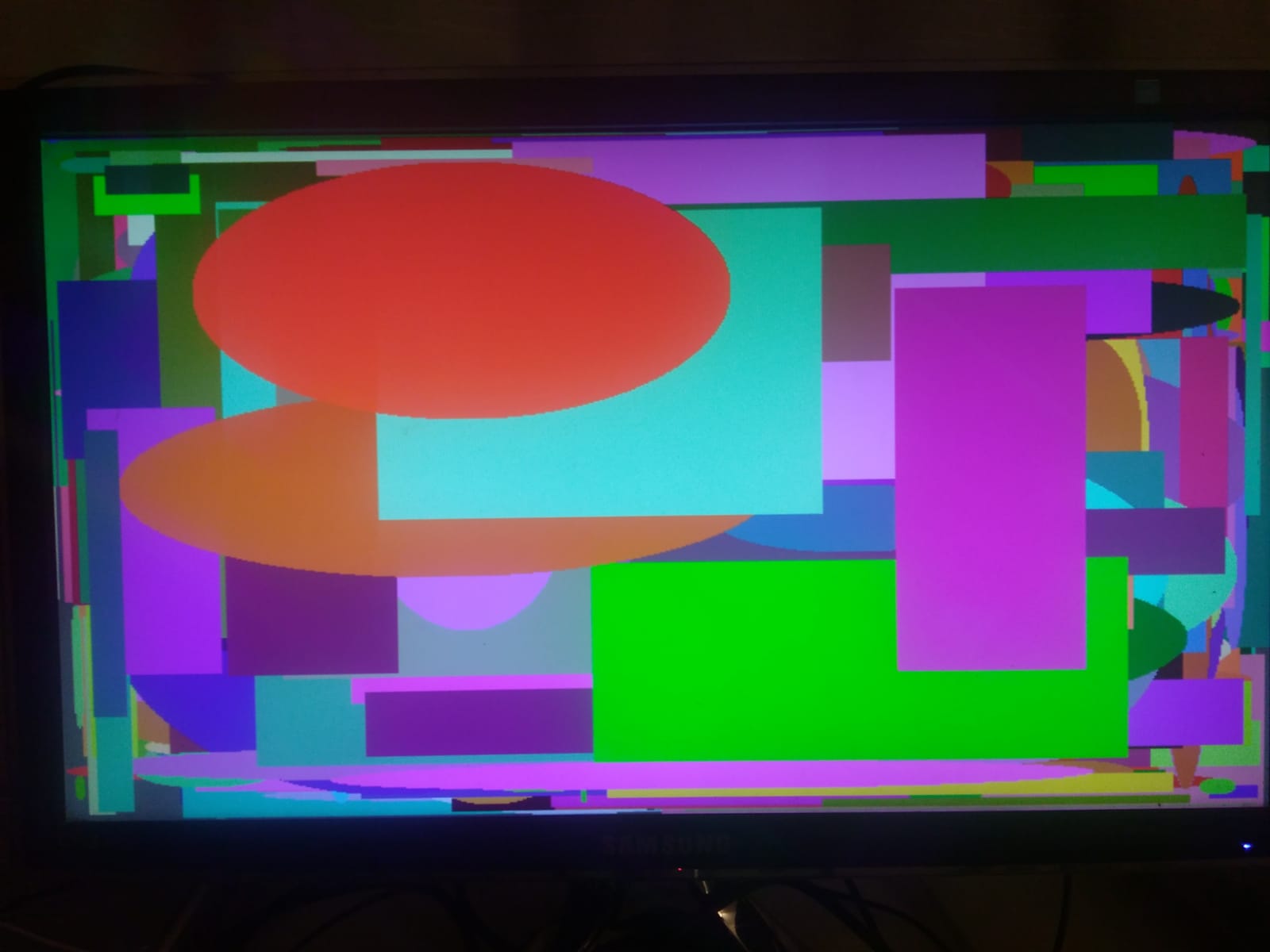
You can visually appreciate that both images seems like the same, but how we can be sure the generated Verilog behaves the same as the software implementation? The solution is to use the acellerated implementations and also call the compiled software implementation in the same SoC, then we can compare if results are the same.
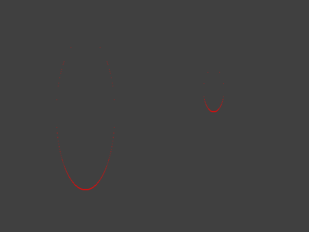
In case of any discrepance, non-matching pixels are marked in red (this was generated by inducing a coordinate error in the software implementation) and the amount of pixels in error is reported.
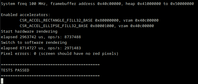
Console output would be in this case:
Pixel errors: 320 (screen should have no red pixels)

==========================================
*** TESTS FAILED ***
==========================================A clock demo application is shown, using a combination of drawn rectangles and ellipses.
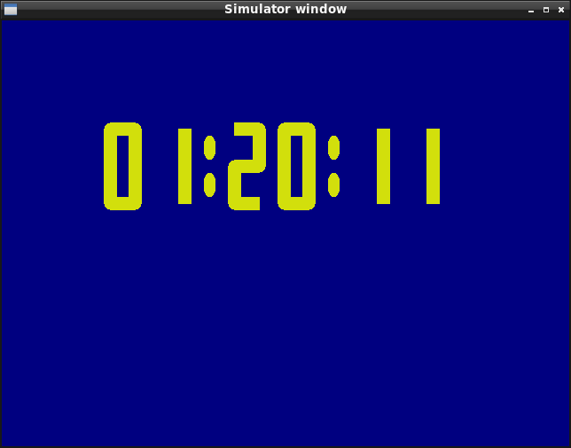
The code for that demo application can be compiled with the main simulator code on the host machine (e.g. Linux) to see results on the simulator window. This eases testing while in development since the program compiles in few seconds, then it can be run on the hardware platform to check if producing the same results. In the provided video, you can see that the hardware matches the simulator.